In my prior post I told about components in my CO2 laser’s RF power supply becoming unsoldered when they overheated. After the repair, I needed some way of retuning the RF output stage for maximum laser output. This motivated me to build the power sensor shown in the picture above.
The concept is simple – The laser’s output is directed at a surface that will almost completely absorb it. This will heat a small slab which has constant heat dissipation on its opposite surface. At steady state, a stable temperature gradient will be established on the slab, so temperature increase detected by the thermocouple should track power input.
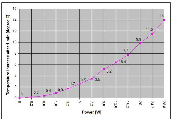
In my power meter, the laser target is a 1.5″ x 1.5″ x 1/8″ piece of anodized aluminum (cut from a transistor heatsink) that is firmly attached to a CPU fan-cooled heatsink. A K-type thermocouple is placed within the aluminum block, under the laser target area. When the fan operates, the CPU cooler sinks heat very well, keeping one side of the aluminum target at virtually constant temperature. I ran a number of experiments, and found out that steady-state is reached at 1 minute of exposure to the unfocused (so as not to burn the anodization) laser beam. For my sensor, the thermocouple’s temperature change over 1 minute of exposure is related to the laser’s power according to the following graph:


Hey nice work!
Im really interested in making this device to test the power output and calibrate a second hand c02 laser I have acquired. Apparently its a Epilog Legend 32EX 120w thats only kicking out 25w
I have found a K type thermocouple and meter with digital display for £5 on ebay… am I right in thinking all I need to do is drill a hole aprox. 1mm in diameter in the side of some 3.2mm anodised aluminium and attach that to a CPU heatsink out of an old computer (I have a graveyard full!) and power up an old fan along side?
Can you give me a more detailed description of the graph, i’m pants at maths but fortunately for me my best mates mum is my old high school math teacher!
Your help would be greatly appreciated. I also have a few other queries for a knowledgeable person like yourself, that I cant seam to answer myself using the internet etc.. to my satisfaction.
I use nichrome wire to create a hot wire at work, using a 140w variant for stick-welding. Its an age old hack that no one ive ever been showed by understands.
Now all it comprises of is a wire 2000mm long in a 18mm wide, 18mm deep channel on an MDF bench with a spring one end and its fixed to a nail the other.
We use a block of sandstone with a hacksaw grove to hold the wire straight
its powered direct from an arc welding transformer using a copper connector.
What I want to know is how do I control the heat, or amperage to shorten the wire, or decrease the heat of the wire, and also would it be possible to use something much easier to find than an arc welder.
IT would be a very useful hack, It would be great if it had a simple variable heat dimmer and timer on off.
Thanks for reading. Im a graphic designer by nature so if theres any way I can help you out back, in that field let me know!
Kind regards
Chris Eccleston